Now getting away from banking, and remembering that I’ve kept my blog as a personal blog first and foremost, here’s an article (hopefully the first of many) on the building of (hopefully) 3 kayaks.
For some time now I’ve been prepping myself for the construction of a fibreglass composite kayak and finally I feel I’m underway! The basic process is to construct a sandwich core with a wood (or other) substrate used to create the form for the kayak with fibreglass on each side providing tensile strength on the inside and abrasion resistance on the outside.
There are two common methods for creating the sandwich core: stitch and glue plywood; and wood strip. I’m starting off with stitch and glue plywood but I have it firmly in mind to go on and create 2 more strip form kayaks. Wife and daughter will surely be bemused as I gift them their own high performance kayak...
The initial kayak is a Night Heron from Nick Schade at Guillemot kayaks. Check the web site and especially the message board he administers. This is an invaluable resource. Once that is done I’ve got my eye on Ross Leidy’s Whiptail, and one of Bjorn Thomasson’s kayaks in particular the Njord, Hunter or maybe Isfjord. No special reason apart from the fact that they just all look so HOT!
So, what about the strongback spacing planner you ask!? Well, when you build your sandwich core form you need a rigid straight guide. This is the strongback and you can create it in a variety of ways. (And no, I don’t need one for the stitch and glue Night Heron but it should make a good flat surface for construction and will suit my needs for the later kayaks.)
The thing is how you go about creating a strongback. I’m very keen on the approach taken by Bjorn Thomasson and Dan Caouette but in building one for myself I used (like Dan) doubled up plywood sheet strips (although in my case I went 150mm wide). The problem is when I went to bend them they seemed in a lot of stress and I wasn’t sure how to even that curvature stress out over the full length. Well, this is where a bit of geometry came in useful and I thought it was worth reporting out for others.
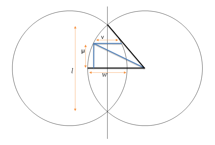
First a diagram; let’s use H to represent the length from the centre to the long end of the strongback, W the distance from the centre to the edge at the widest point (ie half the width), r to represent the radius of the circles that would make up the two sides of the strongback, and h and w to represent the distance up and across at an arbitrary point on the strongback.
How do you get the radius of the circles? Easy thanks to Pythagoras.
So, solve for r to get:
Question is now how to get the width at some arbitrary distance along the centreline of the strongback. No worries,
This time we want to solve for w.
And remember that the width at distance h from the centre is 2w.
Using Excel for my case where I wanted the total length to be 5.00m with greatest width 0.6m I get a table such as this.
| Overall Length | Greatest Width | Circle Radius | Offset from Centre | Width |
| 5.00 | 0.60 | 10.57 | 0.00 | 0.60 |
| 0.50 | 0.58 | |||
| 1.00 | 0.51 | |||
| 1.50 | 0.39 | |||
| 2.00 | 0.22 | |||
| 2.50 | 0.00 |
Applying this to my sample kayak strongback gives me the following drawing.
Update: 9th June 2008: Thanks to the wizardry of Google Docs you can view a spreadsheet:
http://spreadsheets.google.com/pub?key=pYTbzqIDg8t4ncGmXY2EBIw
Or just view the graph here:


2 comments:
To derive the mitre angle to cut the cross pieces in excel: DEGREES(ACOS(h/r)
And to measure the mm different to square (for marking the timber if cutting by hand) Using t to represent the thickness of the crosspiece, and a for the calculated mitre angle: (t/TAN(RADIANS(a)))*1000
This solution has an inherent inaccuracy that it doesn't account for the thickness of the crosspiece, but the error is less than the accuracy of cutting.
Thanks for doing the hard part for us!
Thanks foils, I could've used that myself on the weekend - I was cutting the cross pieces. Unfortunately, no drop saw - broke awhile ago and haven't yet replaced...:(
Post a Comment